
Building Arachne
Everything you need to buy for Arachne v2, and how to put it all together. I realize it looks like a lot, but it really isn’t; I just tried to be as descriptive as possible.
Prices checked October 10, 2026, and they will probably have changed by the time you read this. These are not affiliate links or endorsements, just the parts I used or the closest things I could find on the jungle website.
What it costs
Pretty much everything comes in packs much bigger than one build needs (you need five cup hooks, and the link is for a hundred). If you build one by yourself you buy whole packs, which comes to about $149. The parts that actually end up in each Arachne come to about $60, and the rest goes in your parts bin. The motor, pulley and power supply are sold one at a time, but almost every other listing has enough for at least two, so if you have a friend, build two and split the packs. Each one takes a bit more than half a roll of filament, so two of them take two rolls, which means more colors. Fun!
Parts
| Part | Listing | Use | Pack | Pack price | Each | Per unit |
|---|---|---|---|---|---|---|
| DC gearmotor, 12V 600 RPM, 37mmPick the 12V 600RPM style | Bringsmart JGB37-520 | 1 | 1 | $21.57 | $21.57 | $21.57 |
| Motor speed controller, PWM, with reversing switch | 1203BB, 6-28V 3A | 1 | 2 | $9.59 | $4.79 | $4.79 |
| Power supply, 12V 2A, 5.5x2.1mm plug, center positiveReplaces the SmoTecQ 2-pack, which is unavailable | Security-01 cs-1202000 | 1 | 1 | $9.99 | $9.99 | $9.99 |
| Power jack, 5.5x2.1mm, 11mm panel holeMatches the supply's plug | Panel jack with 18 AWG pigtails | 1 | 5 | $8.19 | $1.64 | $1.64 |
| 6804 bearing | HiPicco 6804-2RS | 1 | 10 | $9.99 | $1.00 | $1.00 |
| 608 bearingsPlus 2 per extra bobbin | SHKI 608-2RS | 3 | 20 | $6.99 | $0.35 | $1.05 |
| 8mm x 150mm rod | Litoexpe linear rod | 1 | 2 | $5.49 | $2.75 | $2.75 |
| Motor pulley, 22mm V, 6mm boreLow stock | HARFINGTON | 1 | 1 | $9.99 | $9.99 | $9.99 |
| Drive belt, 5mm PU roundAbout 240mm per build, plus a 25mm piece for the brake screw retainer | uxcell, 3 m | ~265 mm | 3 m | $8.29 | $2.76/m | $0.73 |
| Brake spring | MroMax tension springs | 1 | 15 | $12.79 | $0.85 | $0.85 |
| M4 square nuts | Waziaqoc 304 SS, 7x7x3mm | 30 | 100 | $5.99 | $0.06 | $1.80 |
| M4 x 12 thumbscrewsOne per flyer hook | uxcell knurled knobs | 4 | 12 | $6.99 | $0.58 | $2.33 |
| 1/2in cup hooksFour flyer hooks and the brake spring; or buy a few loose at a hardware store | Biaungdo cup hooks, gold | 5 | 100 | $4.99 | $0.05 | $0.25 |
| M4 screw kit, 6-30mm, nuts, washersAll the M4 screws and hex nuts | DFDU M4 assortment, 304 stainless | 42 | 706 | $13.99 | $0.02 | $0.83 |
| Rubber feet, 1/2in round | Scotch SP951 clear bumpers | 4 | 40 | $6.59 | $0.16 | $0.66 |
| M3 screw kit, 6-30mm, nuts, washersMotor and speed controller screws, and the controller's nuts | Hincell M3 assortment, 304 stainless | 14 | 1020 | $7.99 | $0.01 | $0.11 |
| Total | $149.42 | $60.34 | ||||
Fasteners
The two screw kits above cover all of these, with some to spare. One M4 kit is enough for one Arachne: if you’re building two, you’ll need a second one, or some extra M4×20 from somewhere. The lengths are checked against the CAD model, so they should be right; if one isn’t, let me know.
| Fastener | Qty | Where |
|---|---|---|
| M4 × 10 socket head, hex nut | 6 | Riser halves, 3 each |
| M4 × 8 socket head | 6 | Spreader to electronics housing. Anything from 8 to 20 works here. |
| M4 × 12 socket head | 2 | Flyer arms, inner holes |
| M4 × 16 socket head | 10 | Front riser to electronics housing (6), spreader to brake screw retainer (4) |
| M4 × 20 socket head | 10 | Brake screw retainer to rear riser (4), brake spring retainer to rear riser (2, with hex nuts), spreader to rear riser (2), flyer arms, outer holes (2) |
| M4 square nut | 30 | Brake screw retainer (8), electronics housing (12), spreader (2), flyer arms (4), flyer hooks (4) |
| M3 × 12 socket or button head | 6 | Motor to front riser. No washers, or the heads hit the pulley. |
| M3 × 10 socket head, hex nut | 4 | Speed controller |
Optional hardware and tools
The parts list uses 304 stainless for all the screws and nuts, the same as Clotho’s. If you’d rather have black, the black oxide versions of the same sizes are below, for about the same money.
Soldering is optional on Arachne. The motor comes with spade terminals you can crimp onto its wires instead, and the power jack comes with wires already on it; soldering longer ones on lets you mount it in a tidier spot, but there’s a place for it either way.
| Part | Listing | Use | Pack | Pack price | Each | Per unit |
|---|---|---|---|---|---|---|
| Black M4 screw kit, 6-30mm, nuts, washersIn place of the stainless M4 kit | Kernmax M4 assortment, black oxide | 42 | 520 | $7.99 | $0.02 | $0.65 |
| Black M3 screw kit, 6-30mm, nuts, washersIn place of the stainless M3 kit | Kernmax M3 assortment, black oxide | 14 | 950 | $6.99 | $0.01 | $0.10 |
| Soldering iron kit, if you don't have oneFor the jack, and the motor if you don't crimp | 60 W adjustable soldering iron kit with stand and solder | 1 | 1 | $13.99 | $13.99 | $13.99 |
| Crimper for insulated terminalsFor the motor's spade terminals, which come with it | Plustool ratcheting crimper, AWG 22-10 | 1 | 1 | $16.99 | $16.99 | $16.99 |
From your shop
- Filament. A bit more than half a roll for each Arachne. Most of it works fine in PLA (see Printing), and since most of the parts are small, it’s a good way to finish off those nearly empty rolls.
- A couple feet of 18 AWG stranded wire.
- About 300 mm (12″) of cotton twine for the brake.
- A bit of sandpaper, a couple of square inches of 180 grit or so.
Build guide
Most of this should be fairly intuitive once you have the parts in your hands. All the holes and recesses are the right size, and the wrong parts won’t fit or will just look silly. Screw lengths are in the fasteners table above, and the steps call them out where it matters.
The drawings are made from the CAD model. Each one shows the parts that step adds, pulled apart along the way they go together, with a parts list. The latest version of this guide, with color renders, is at thunderbirdlabs.com/arachne-build.html, and the files are on Printables (printables.com/model/1526904).
The pictures are made from the CAD model: a render on the left and an exploded drawing with a parts list on the right (click either one to see it bigger). The parts you’re adding in that step are gray, and the ones you’ve already put together are in color. There’s also a printable PDF of this page, with just the drawings.
Tools
- A handful of appropriate Allen keys (the screw kits come with them, but nicer ones are…nicer)
- A pair of needle-nosed pliers
- A pair of long tweezers (or just use the pliers)
- A small soft-blow hammer
- A small screwdriver, for setting the square nuts (or use a small Allen key)
- A crimper or a soldering iron (soldering is optional but preferred)
- A heat gun, for joining the belt
Printing
- Many of these parts need fairly tight printing tolerances. To test your printer, load the bobbin assembly and cut off the threaded ends of the flanges in your slicer. They should screw together with little resistance. If they don’t, tune your print settings before moving on.
- 0.20 mm layers, 5 perimeters, 5 top and bottom layers, and an isotropic infill (gyroid or cubic). Use the Arachne perimeter generator in your slicer for cosmic symmetry.
- All the parts are provided in assemblies and need no supports as oriented. Print one of each, except the alternate brake screws (the brake step tells you whether you need one) and the rear saddles, which are optional.
- The risers come in two assemblies, the facing sides in one and the away sides in the other, so you can print the faces in a different color or material from the backs.
- Most of these parts work well in PLA, though PLA+ or PETG are still preferred. PLA (especially silk PLA) can be brittle and crack when you press the square nuts in, so print at least the flyer arms in PLA+ or PETG; they take a fair amount of stress and flex. That said, PLA comes in more fun colors and has worked fine in my (somewhat limited) testing. If your PLA parts crack, print them again in PLA+ or PETG, and tell me about it in the comments so others can learn and I can redesign the troublesome parts.
- For extra bobbins, just print the bobbin assembly again, and get two more 608s for each.
- The flyer takes four hooks, and the flyer assembly file has all four.
- The STEP file is the entire CAD model. Your slicer will happily load it and try to print it…but maybe don’t.
Prepare the rod and bearings
With the cheap 608s on the parts list, the rod usually needs little or no prep, but check yours before anything goes together.
- Cheap 8 mm rod is usually sheared to length rather than ground, which crushes the last centimeter or so of each end even though it measures a true 8.00 mm in the middle. If a 608 won’t slide on and off the end by hand, wrap the rod in something to protect it, chuck it in a drill, file a light chamfer (about 0.25 mm) on the end, and work it down with 180 grit until the bearing slides. If a bearing won’t go on, suspect the rod first.
- Cheap 608s tend to come packed with grease thick enough that the rod spins in the inner race instead of the balls rolling. A jar of alcohol and a shot of silicone spray takes care of that.
Wiring
There isn’t much of it. The speed controller does all the work: power goes in, the motor comes out, and the knob and the forward/off/reverse switch are already part of it. There’s no firmware, nothing to set, and no wiring diagram needed.
- Solder or crimp. The motor comes with two spade terminals for its tabs; crimp them onto about 150 mm (6″) of 18 AWG wire, or solder the wire straight to the motor’s tabs. Leave it a bit long if you like; it’s easy to trim later, and there’s room to tuck the extra.
- Holes first. If a wire has to go through a hole, put it through the hole before you solder or crimp the other end.
- The controller’s terminals. The controller has one green four-screw terminal block. With the terminals facing you, they go Motor−, Motor+, Power+, Power− from left to right; the board is marked OUT at the motor end and IN at the power end.
- Polarity. The power supply is center-positive, and on the jack the red wire is positive and the black one negative, so red goes to Power+ and black to Power−. Get those right. The motor’s two wires go to Motor+ and Motor−; the switch reverses the motor anyway, so if you swap those, the only difference is which side of the switch is which. Since the switch is symmetrical, you can just pop it out and turn it over, no need to rewire.
Risers, base and electronics
- Press the halves of each riser together by hand to check the alignment, then gently tap them into place until there are no gaps. They should fit tightly everywhere except near the bearing saddles, where a little flex is fine; they get bolted together next.
- Press three M4 hex nuts into the recesses on the inside of each riser (tap them in if you need to), and bolt each riser together with three M4×10.
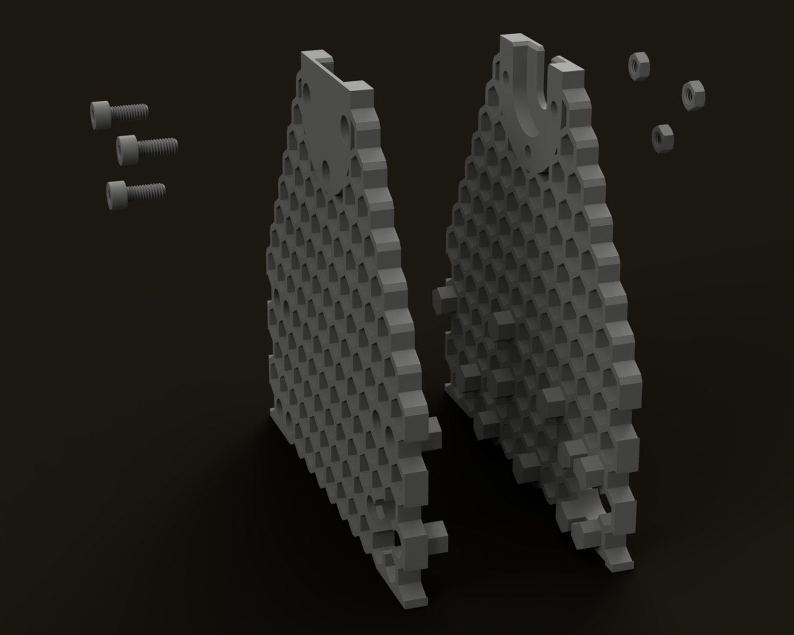
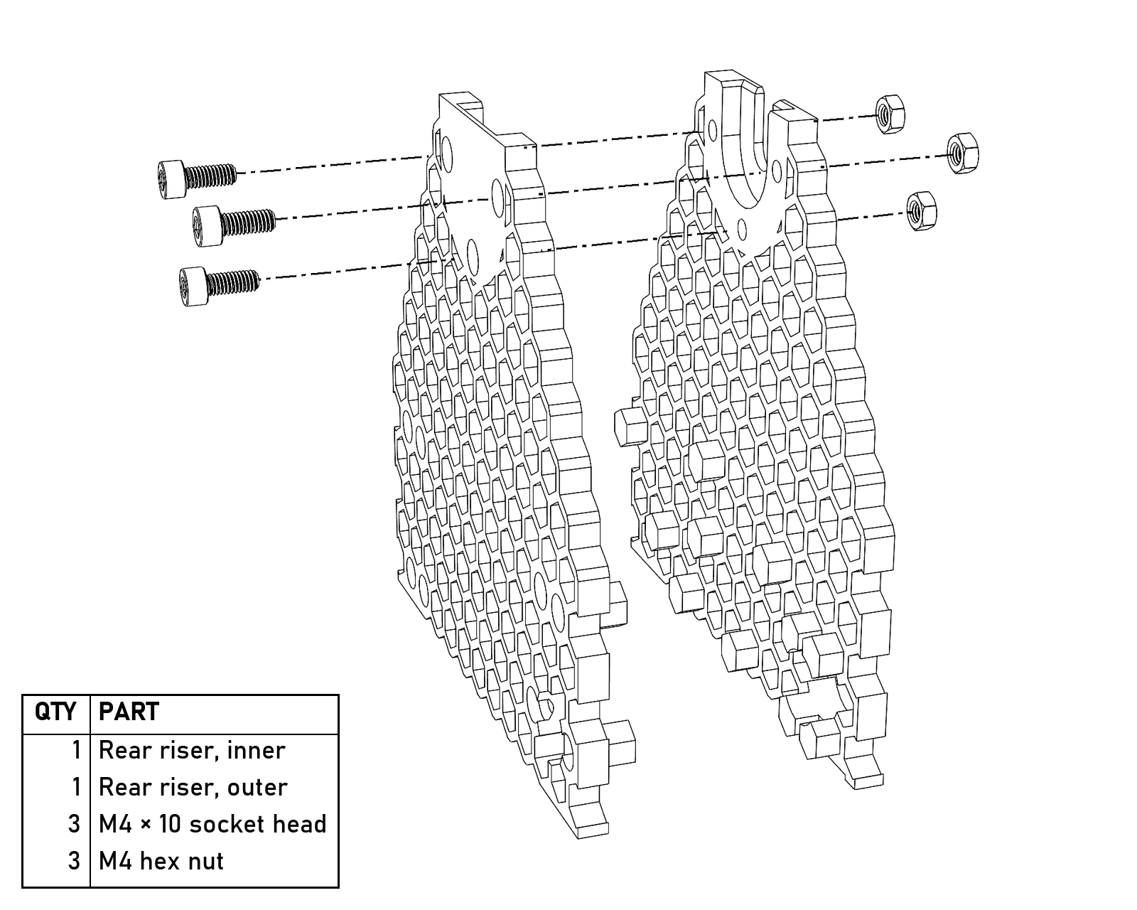
The rear riser: two halves, three M4×10 and three hex nuts. The nuts go in from the inside face.
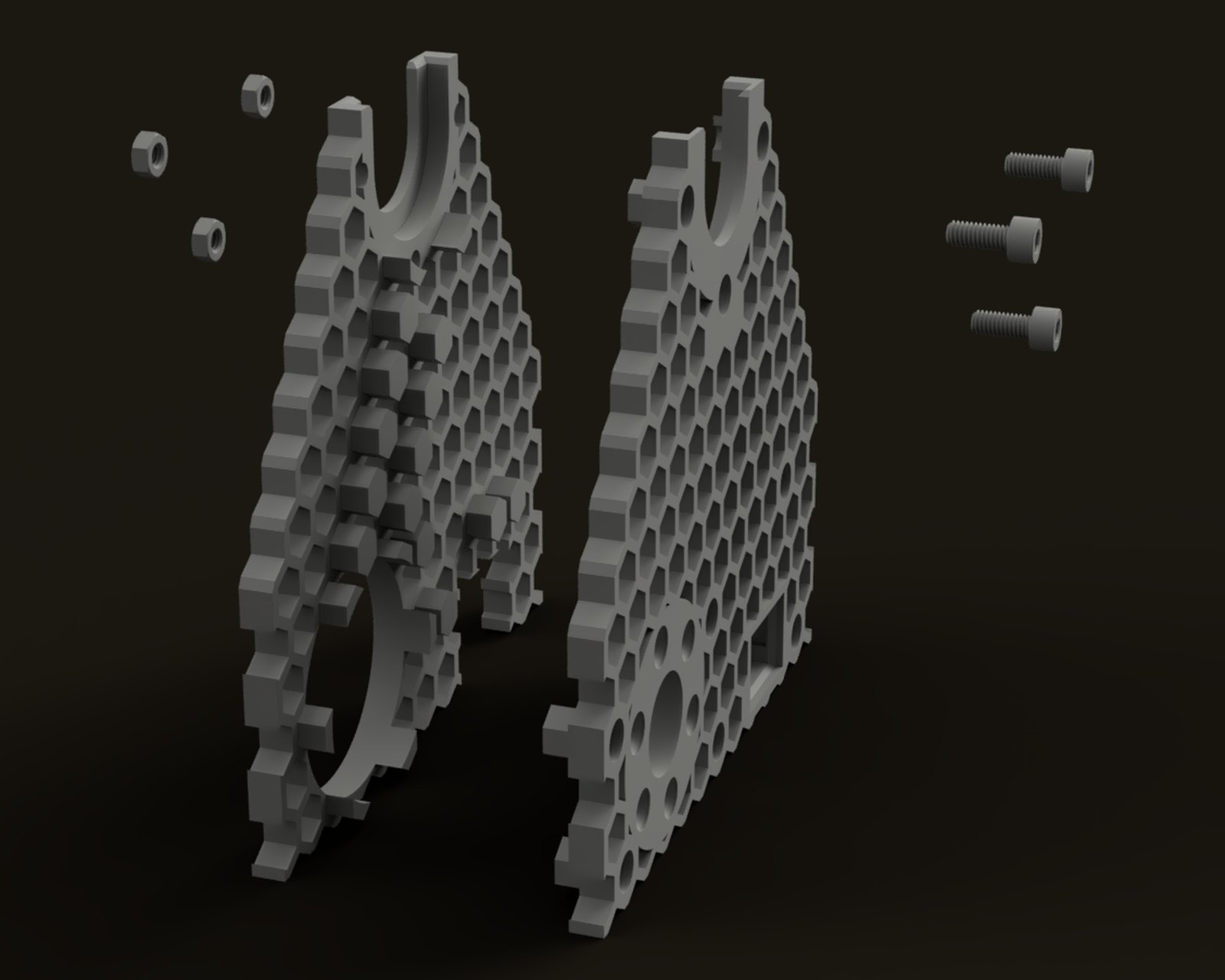
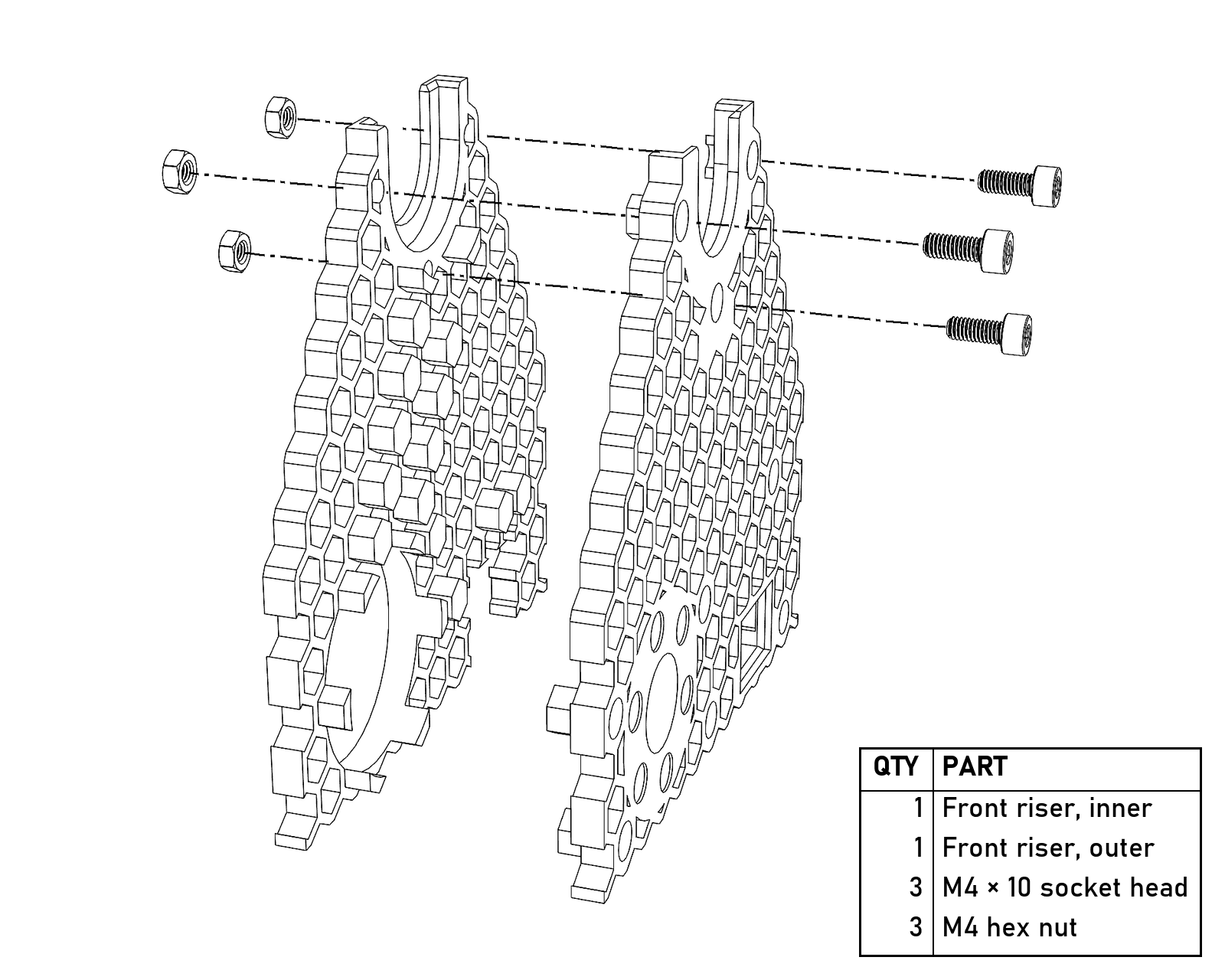
The front riser goes together the same way.
- Attach the motor to the front riser with six M3×12, socket or button heads, and no washers; washers stick out far enough to hit the pulley. Don’t use longer screws or overtighten them, or they’ll damage the gearbox. Afterwards, turn the motor shaft by hand to make sure the screws aren’t hitting anything inside.
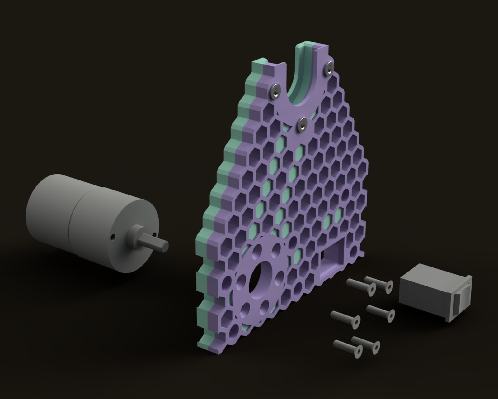
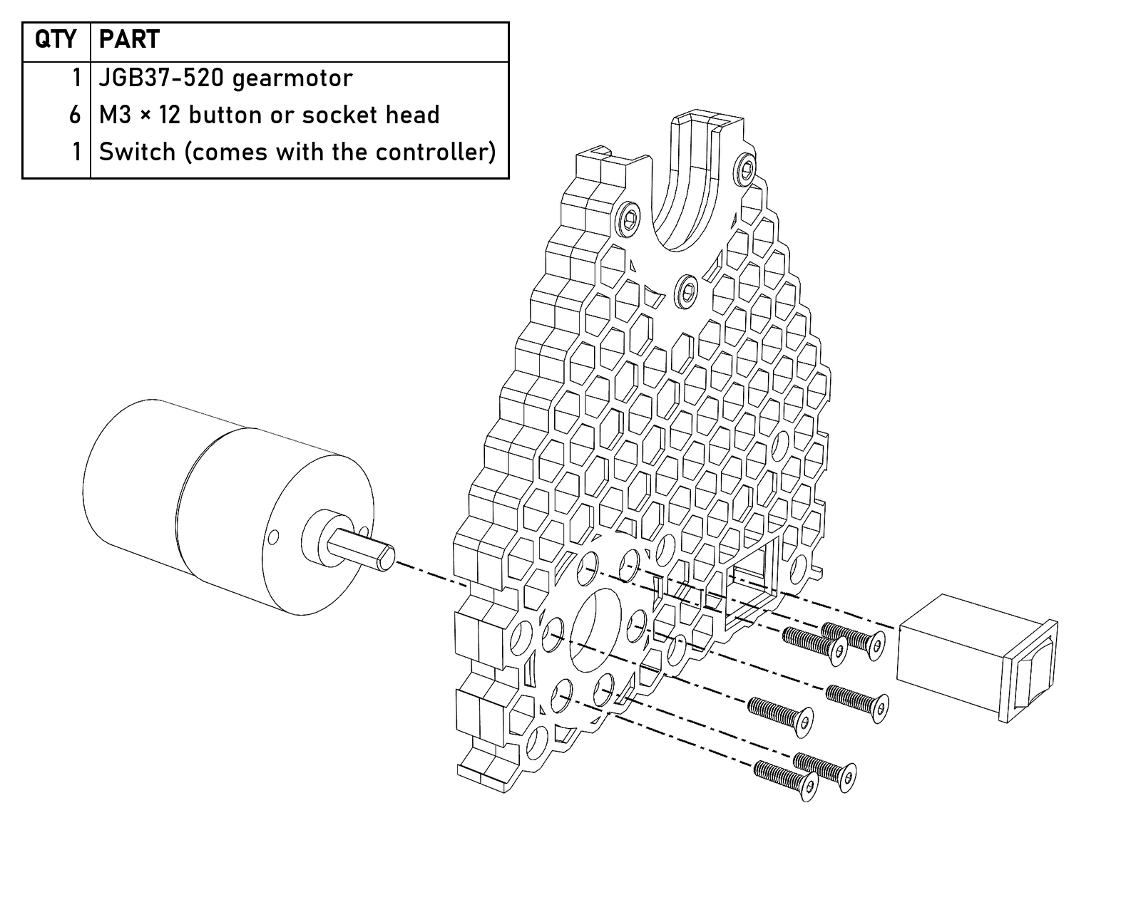
The motor and its six M3×12 go on from opposite sides of the front riser, and the switch (step 8) presses in from the front. The pulley isn’t shown here; it’s in the picture at step 16.
- Put the pulley on the motor shaft with the grub screws that come with it. One of the grub screws should be on the flat of the shaft.
- Line the rear fascia up over the rear riser, press it on by hand to check the alignment, then gently tap it into place.
- Screw a cup hook into the small hole in the brake spring retainer. Press two M4 hex nuts into it and bolt it to the rear riser with two M4×20.
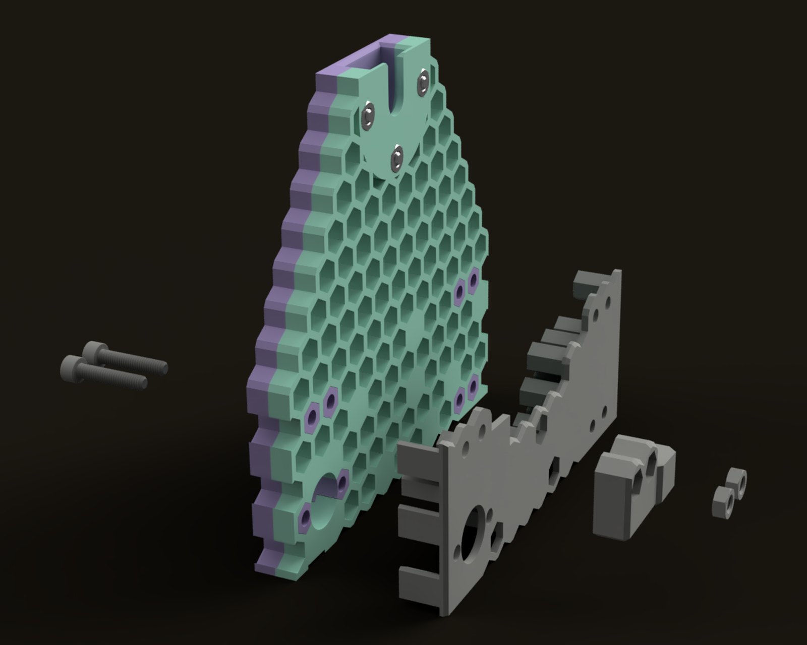
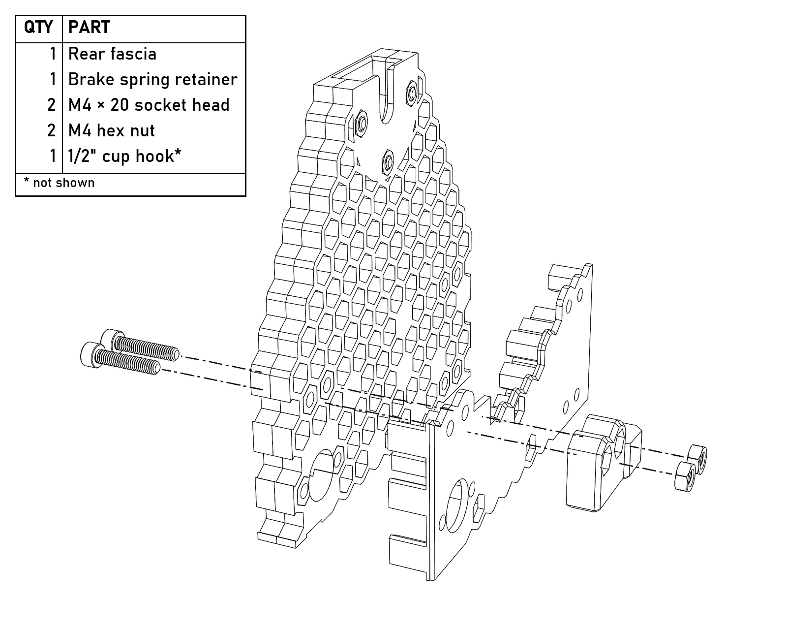
The rear fascia and the brake spring retainer. The two M4×20 go in from the back, through the riser and the fascia, into the hex nuts in the retainer. The cup hook isn’t shown.
- Press eight M4 square nuts into the recesses in the brake screw retainer. Use the needle-nosed pliers, the hammer and the small screwdriver as needed. Make sure it’s the current brake screw retainer, the one with a slot in the threads (it’s its own file). Bolt it to the rear riser with four M4×20.
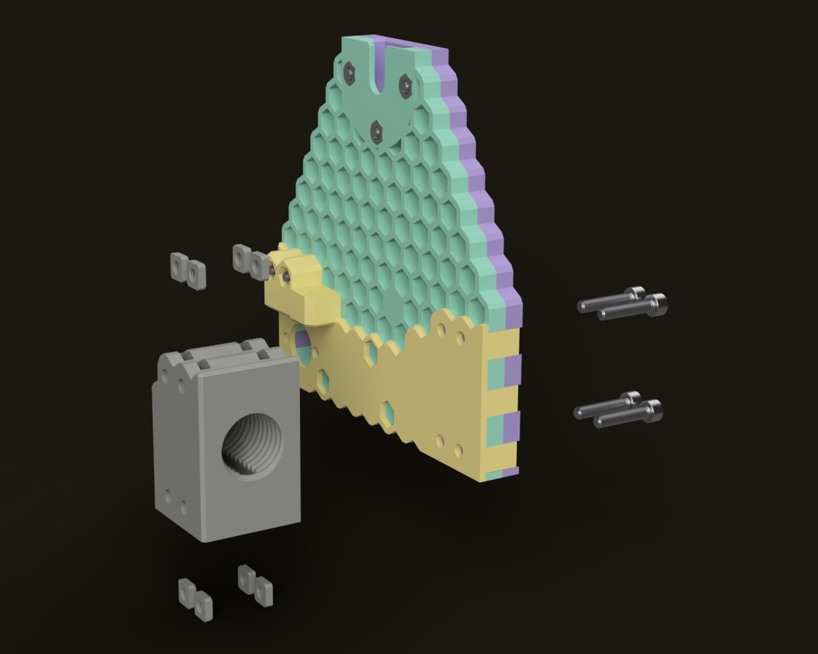
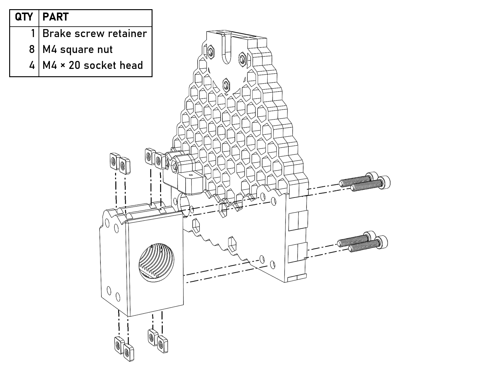
The brake screw retainer. Four square nuts drop into the slots on top and four go into the slots on the bottom, and the four M4×20 go through the rear riser from the back.
- Take the heat shrink off the controller’s switch and press the switch into its recess in the front riser. It should click firmly into place.
- Wire the motor (see Wiring).
- The power jack can go in one of two places. If you can solder, take the heat shrink off the jack, desolder the wires it came with, and solder on about 250 mm (10″) of 18 AWG; then it goes in the spreader arm. If you’d rather not solder, it goes in the hole at the base of the spreader instead, with the wires it came with.
- Grab the spreader and the jack hole plug from the base assembly. Thread the jack’s wires through whichever hole you’re using and screw the jack into place, then screw the plug into the other hole.
- Connect the motor and the power jack to the speed controller, minding the polarity.
- Optional, but a good idea: gently plug in the switch and the power and test it. The switch should reverse the motor, the center position should stop it, and the knob should control the speed. Unplugging the switch afterwards may make the next few steps easier, but either way be careful; that wire is delicate.
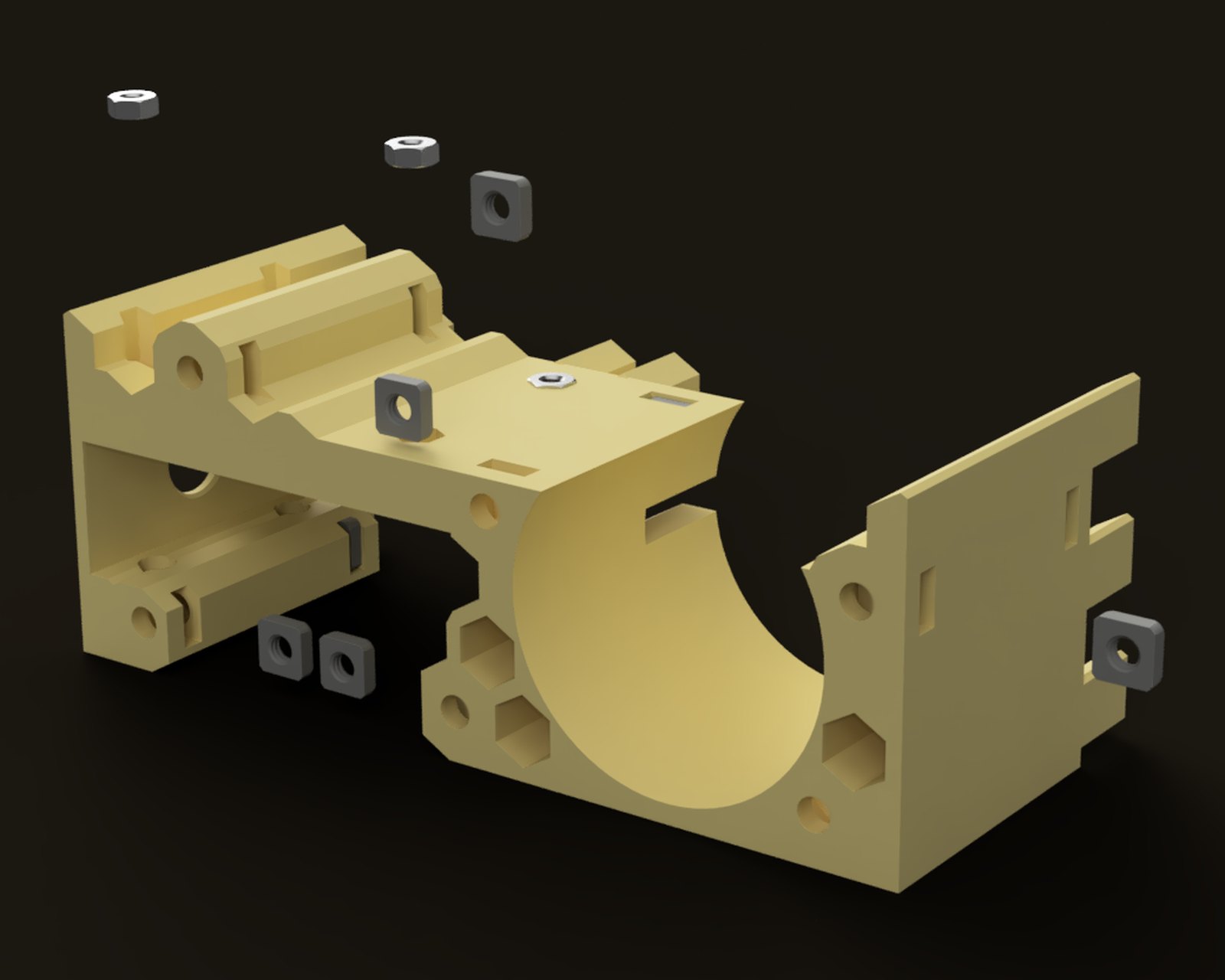
- Press four M3 hex nuts and twelve M4 square nuts into the recesses in the electronics housing.
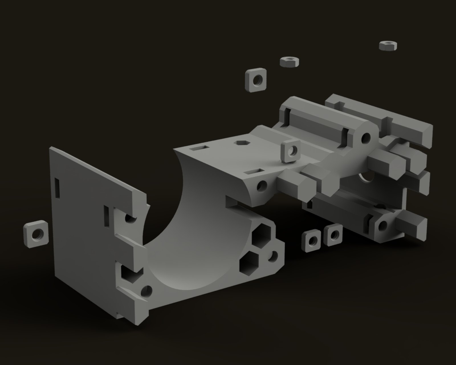
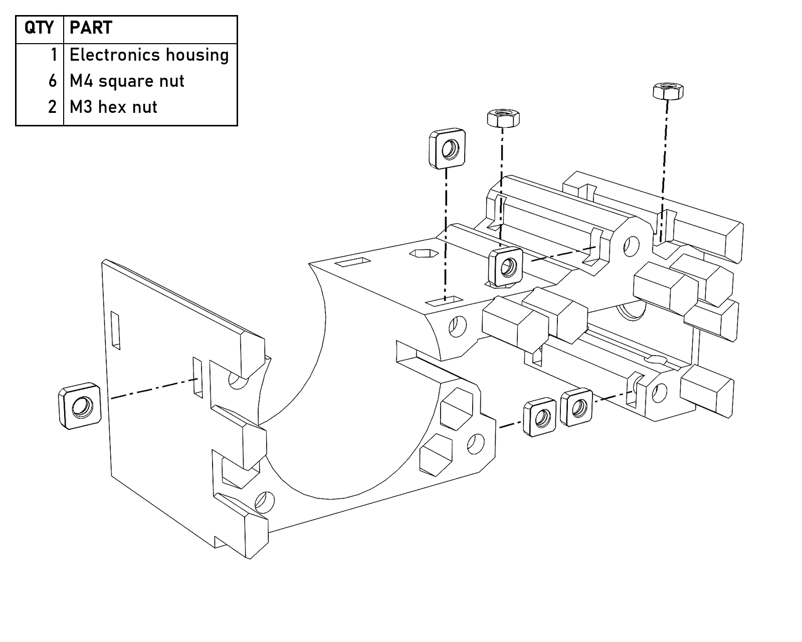
The nuts for the front wall of the housing, from the front. Each one is pulled out the way its slot opens.
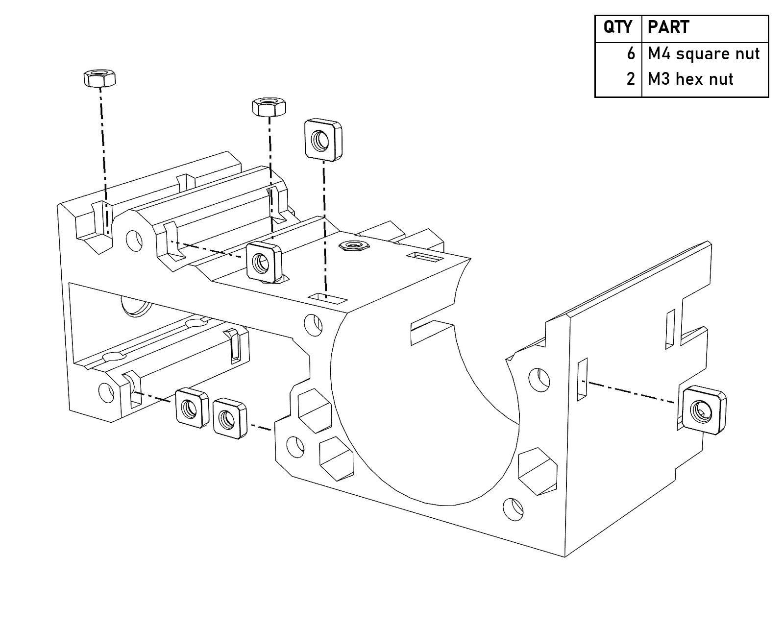
The nuts for the back wall, from the back, and the other two M3 nuts.
- Pass the controller’s pot shaft through the hole in the electronics housing and fasten the controller with four M3×10. You may need the tweezers to place the inside screws, since it’s a bit tight in there. There are holes in the bottom of the housing to get an Allen key through to tighten them.
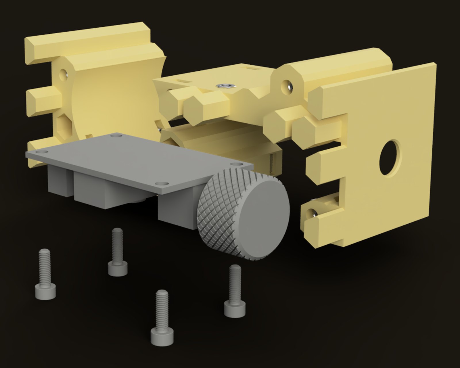
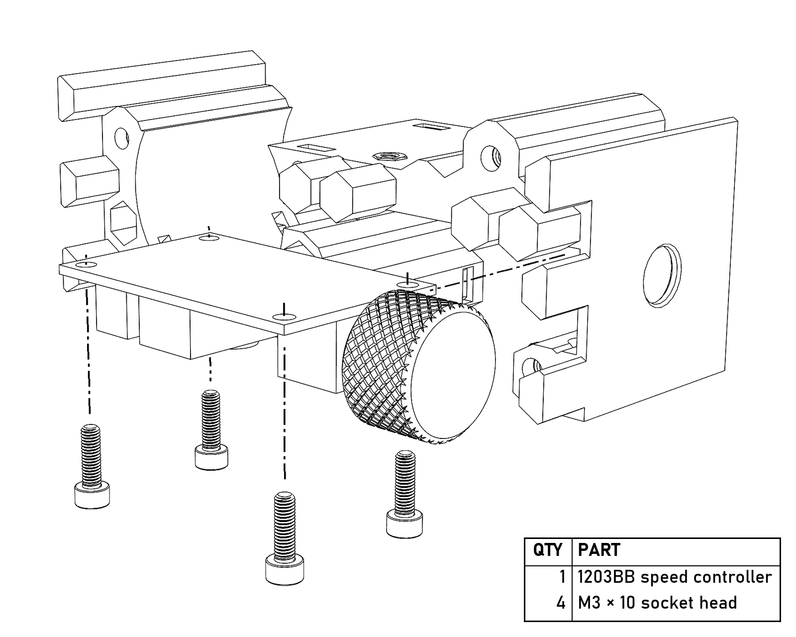
The controller goes in through the front of the housing with its pot shaft out the side, and the four M3×10 come up from underneath into the M3 nuts.
- Make sure the motor wires pass through the slot in the electronics housing and the switch wires aren’t being pinched, then bolt the front riser to the electronics housing with six M4×16.
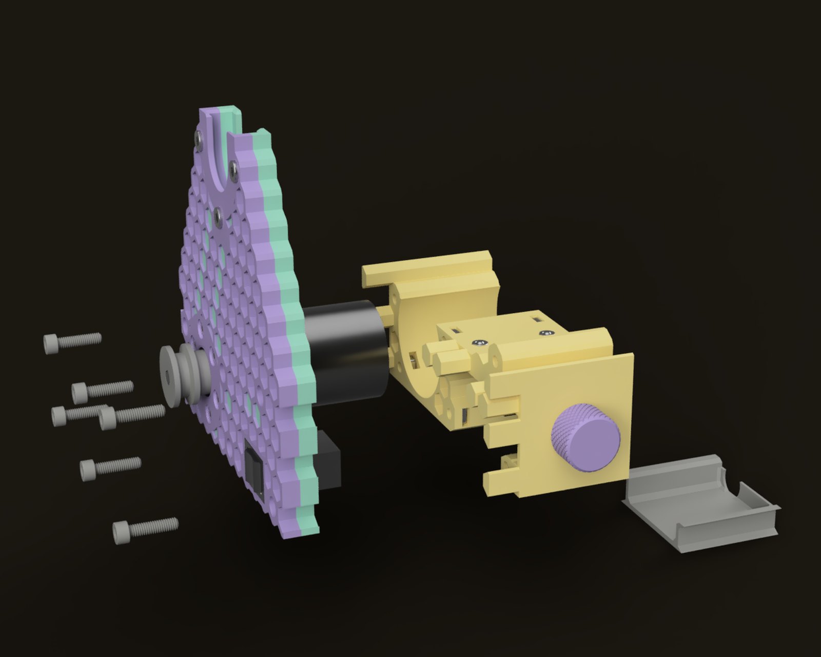
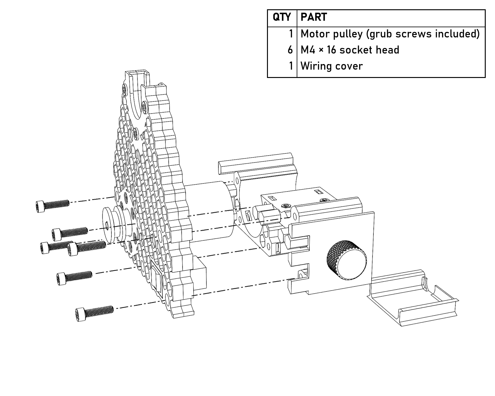
Six M4×16 from the front, through the riser into the housing, and the wiring cover (step 18). The pulley is on the motor shaft here.
- Plug the switch into its socket on the controller.
- Slide the electronics cover into place over the electronics, making sure it goes all the way in and doesn’t pinch any wires. The recess in the bottom of the cover goes toward the front riser.
- Bolt the spreader to the electronics housing with six M4×8. Really, any length from 8 to 20 works here; 8s can be tough to get started, but this is a place to use whatever you have a lot of.
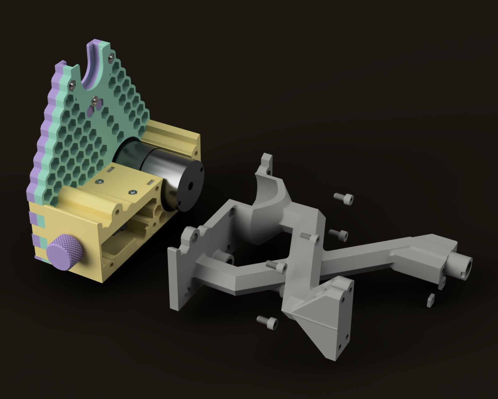
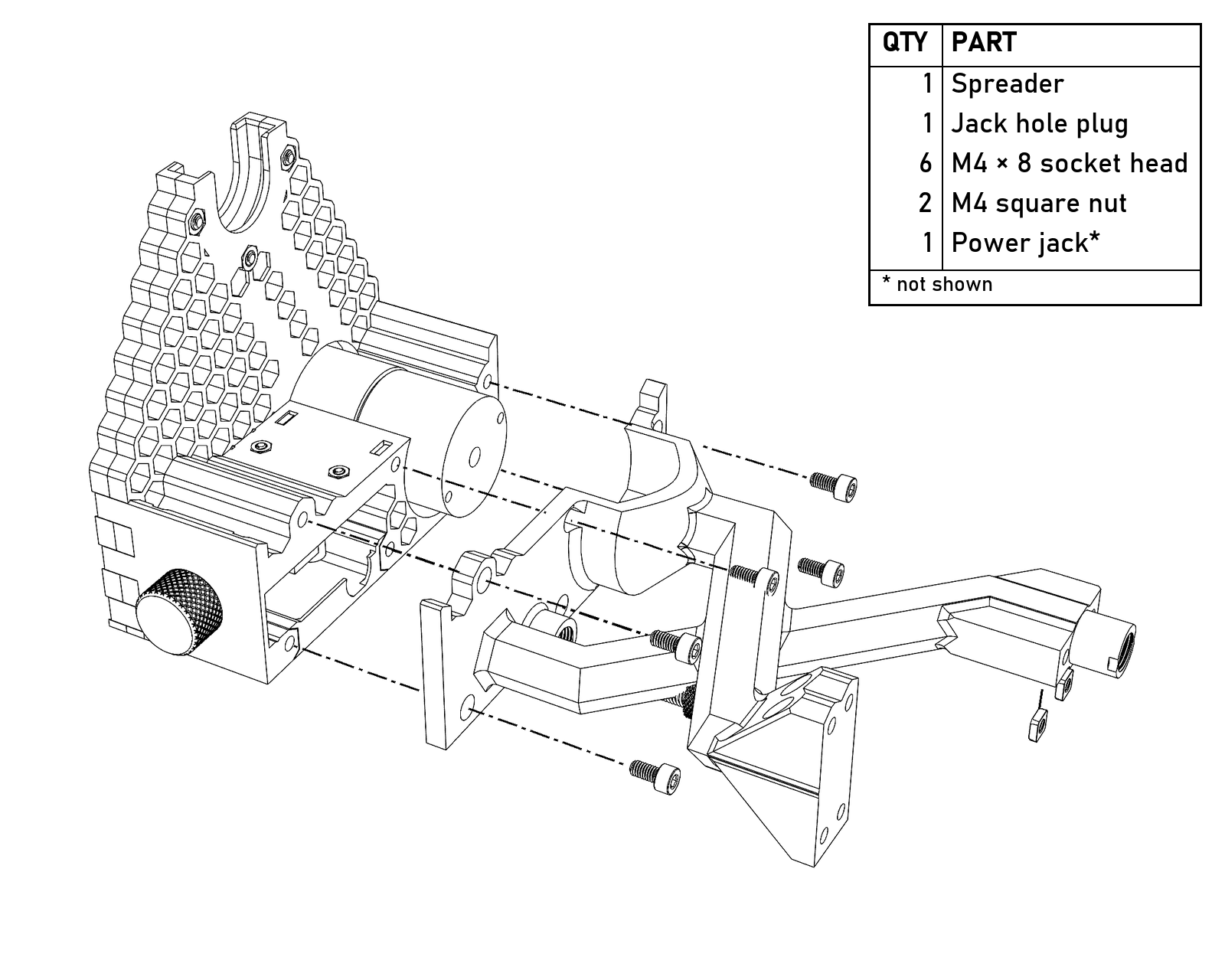
The spreader and the jack hole plug. The six M4×8 go in from inside the spreader, and the two square nuts for the rear riser screws go in from underneath. The power jack isn’t shown.
- Press two M4 square nuts into the spreader for the rear riser screws, then bolt the spreader to the rear riser with two M4×20, and to the brake screw retainer with four M4×16.
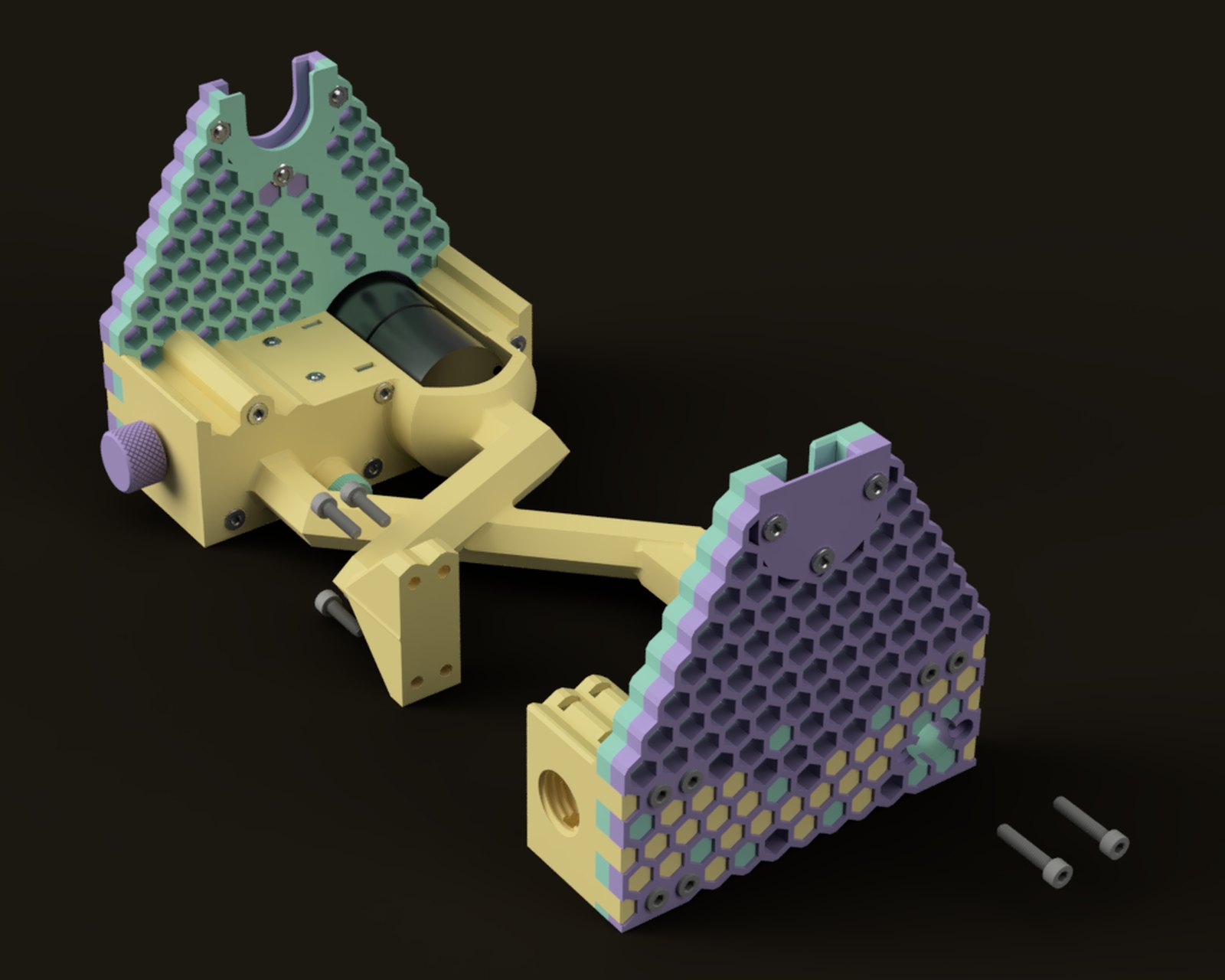
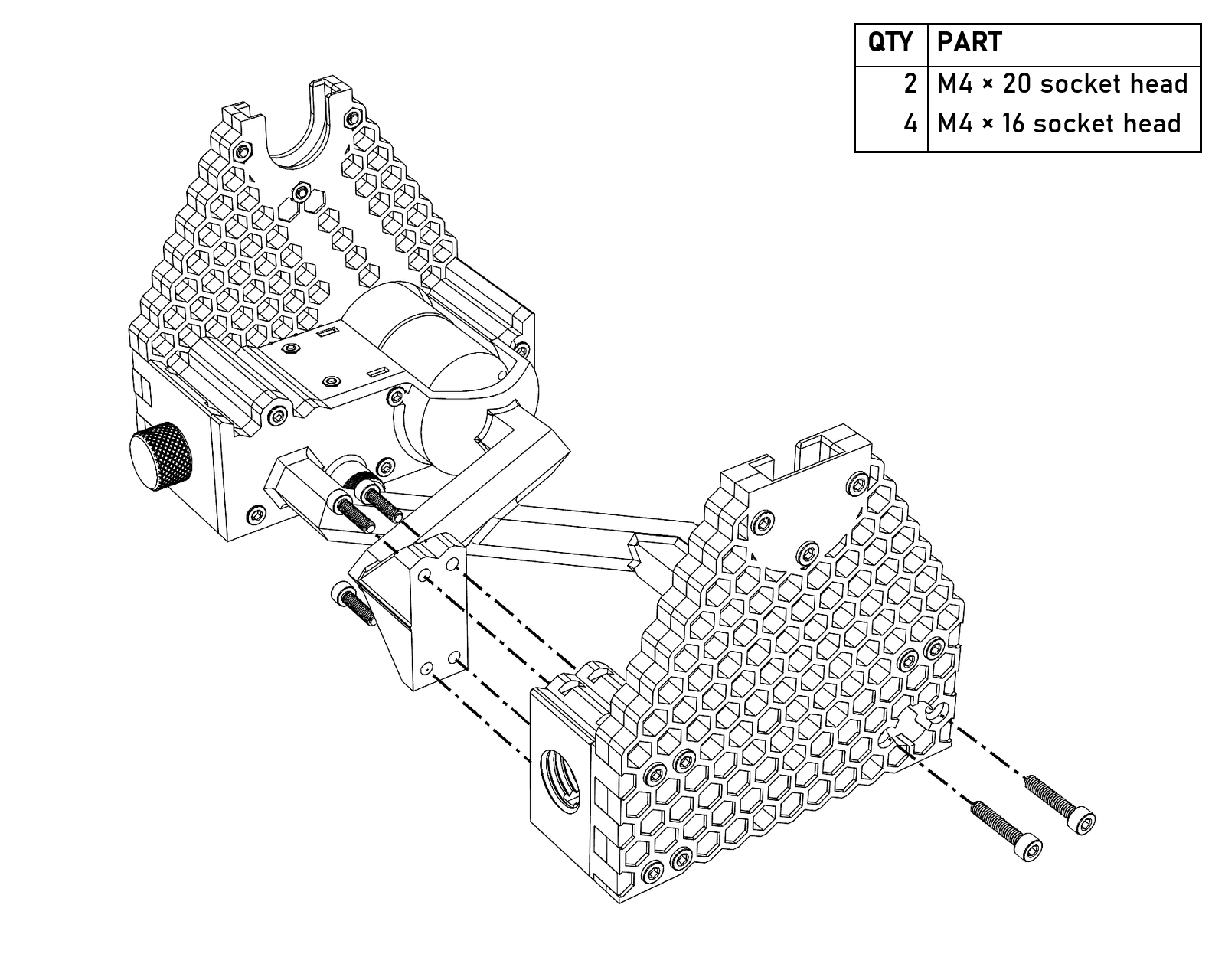
The rear riser goes on last: two M4×20 from the back into the spreader’s square nuts, and four M4×16 from inside the spreader into the brake screw retainer.
- Stick four rubber feet into the recesses on the bottom: two at the front, under the electronics housing and the wiring cover, and two at the back, under the rear riser and the brake screw retainer.
- Press the printed knob onto the pot shaft.
- Plug in the power and test everything again.
Flyer and bobbin
- With the flyer body on a smooth, hard surface, gently tap the rod into its recess. It may take a bit of force, but you should hear the sound change when the rod bottoms out. If you’re not sure it’s all the way in, put the orifice on (the next two steps) and set the flyer in the base: there should be less than 1 mm between the end of the rod and the rear riser. If there isn’t, take the orifice back off and tap it some more.
- Put two M4 square nuts into each flyer arm and attach the arms to the flyer body with M4×12 in the inside holes (toward the orifice) and M4×20 in the outside holes.
- Onto the threaded end of the orifice put a bearing spacer, the 6804 bearing, and the second bearing spacer, in that order. Screw the orifice into the flyer body.
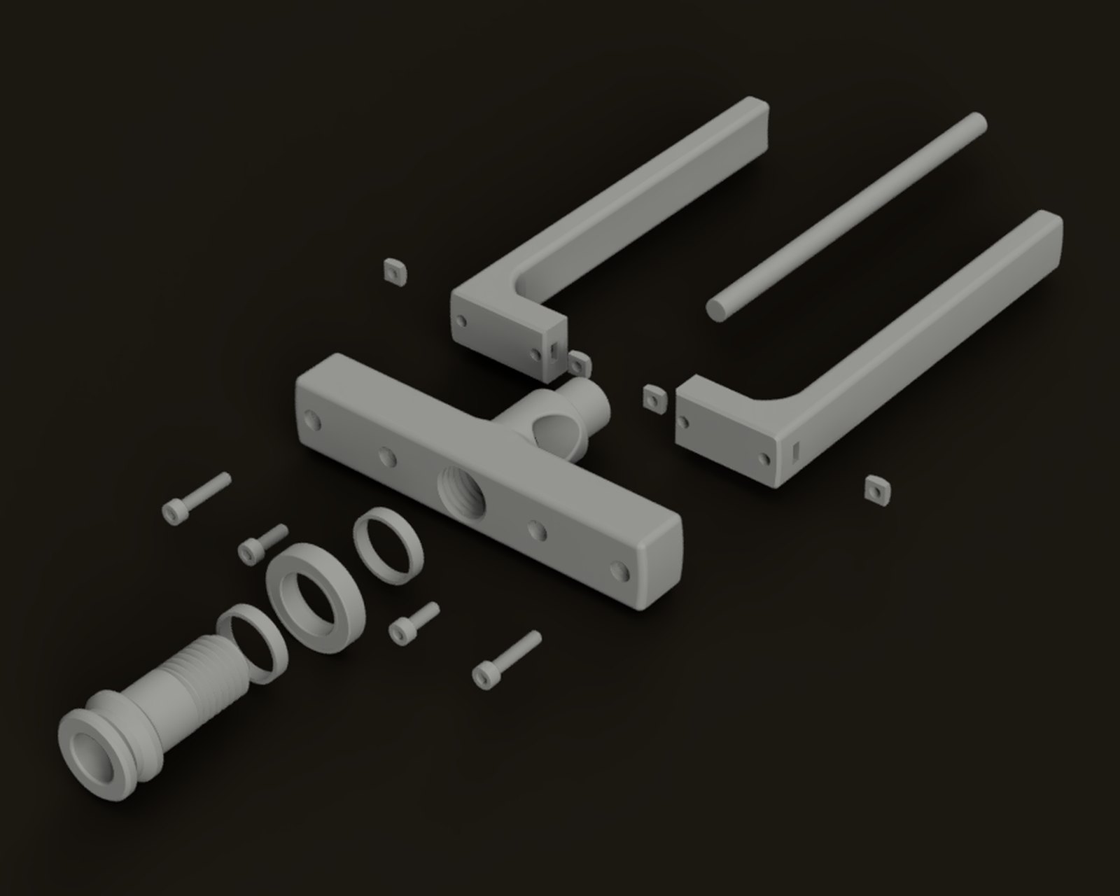
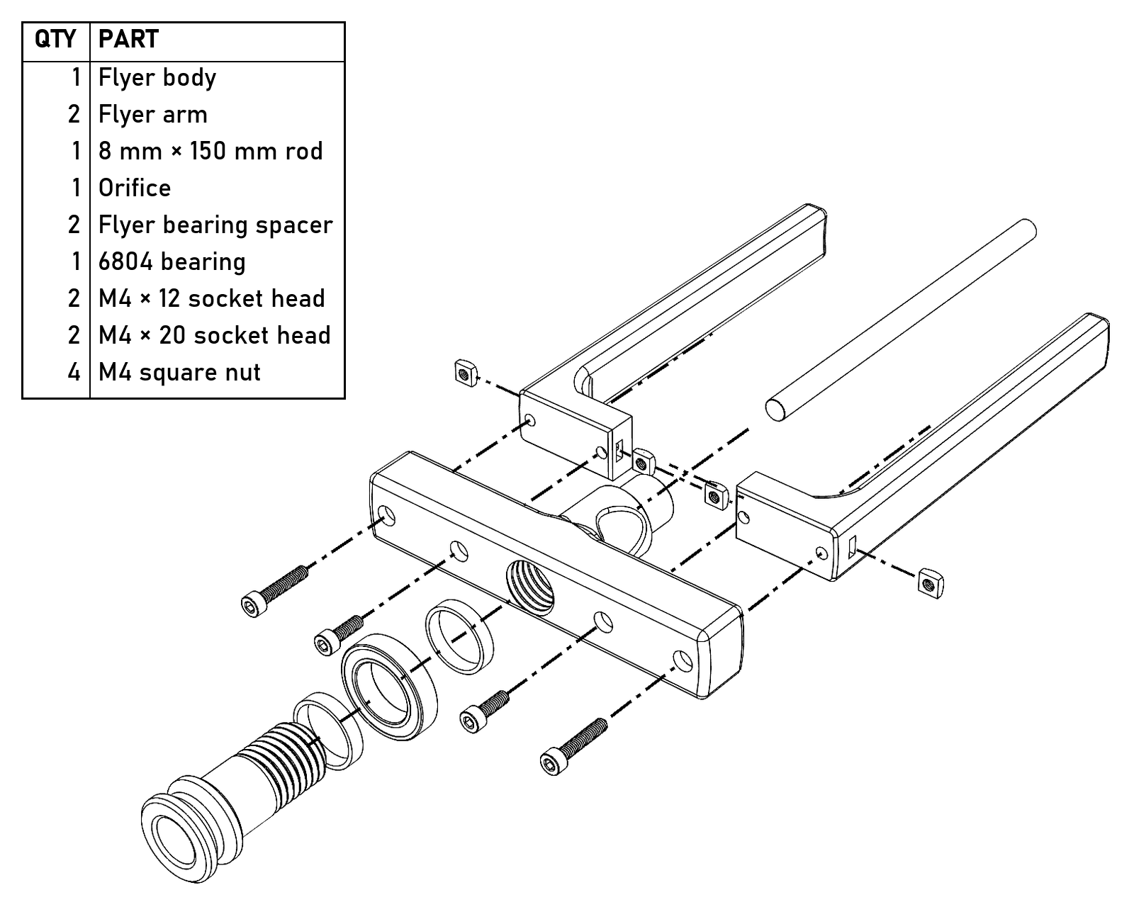
The flyer: the rod, the arms with their square nuts, M4×12 in the inside holes and M4×20 in the outside ones, and the orifice with the 6804 between its two spacers.
- Test-fit the flyer hooks on the arms. They should slide smoothly with very little friction; if they catch, lightly sand the arms with 180 grit until they don’t. Sand them under running water to keep the dust down, or rinse them afterwards to get rid of the powder and bring back their factory sheen.
- The flyer takes four hooks, two on each arm. With only one per arm the flyer goes out of balance as soon as the hooks aren’t in matching spots, and it gets worse the faster you spin. Thread a cup hook into the small hole in each flyer hook, press an M4 square nut into each one, and start an M4×12 thumbscrew, keeping the tip out of the arm slot. Slide the hooks onto the arms and secure them with the thumbscrews. It takes very little force; don’t overtighten them.
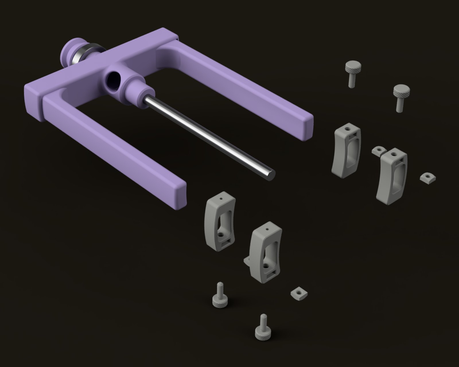
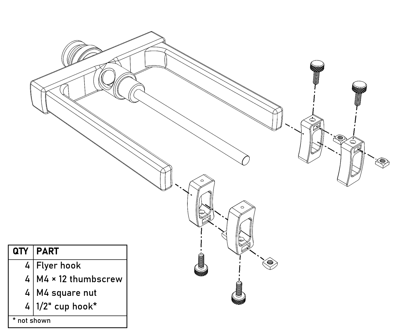
Four hooks, each with a thumbscrew and a square nut. The cup hooks aren’t shown.
- For the bobbin, press a 608 into the front flange and screw the rear flange into it. Press the bearing spacer into the rear flange, press the second 608 in after it, and screw on the rear bearing retainer.
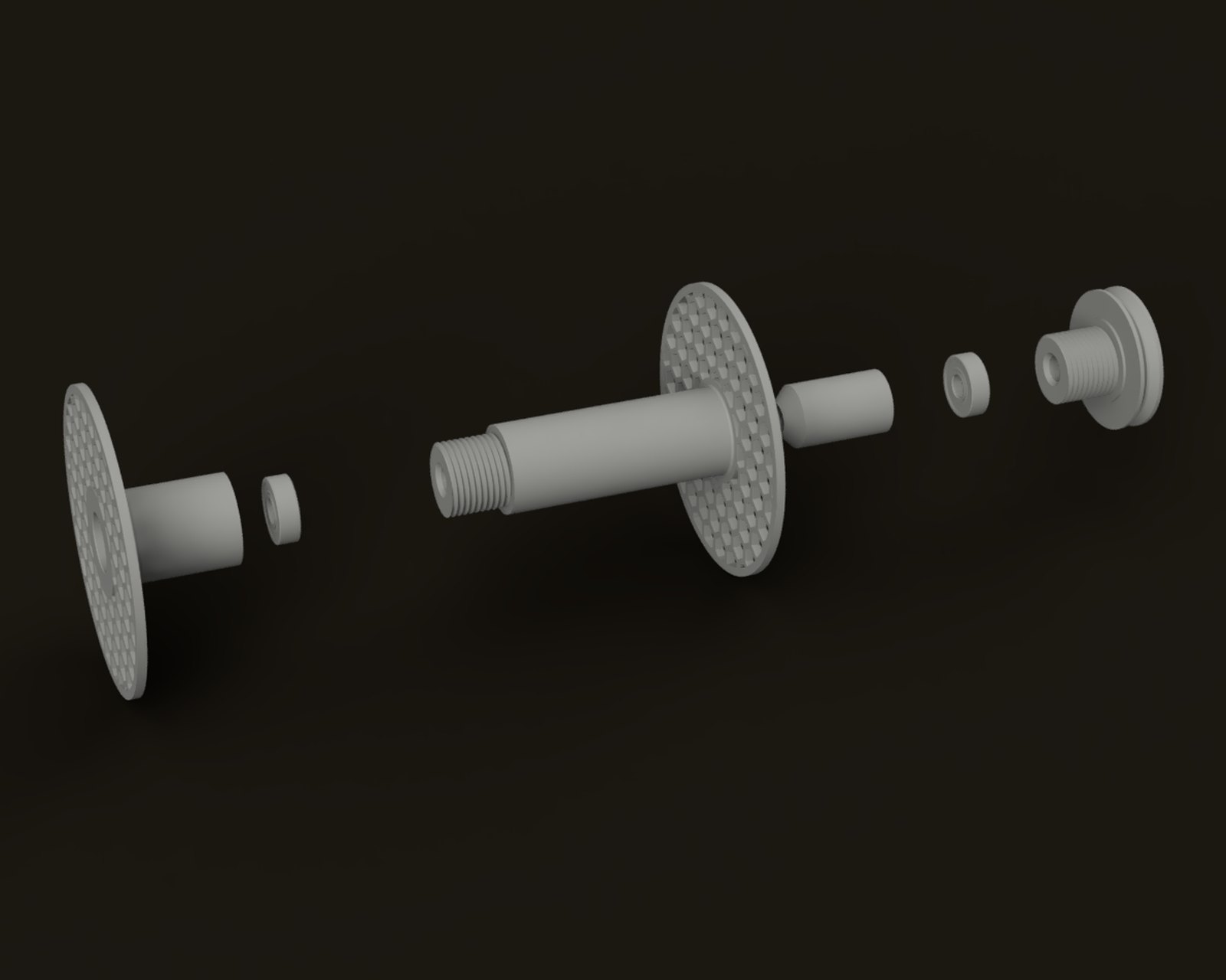
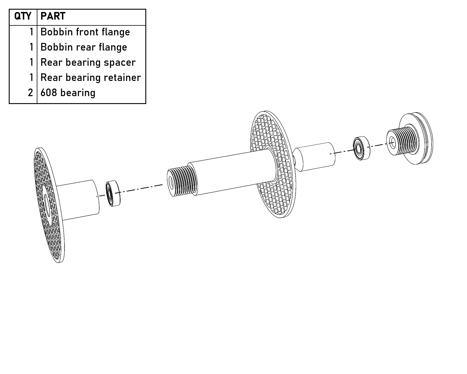
The bobbin, the same one Clotho uses.
Final assembly
- Screw the brake tension screw into the brake screw retainer. It may be very hard to turn at first, but it should thread in without damage, and it wears in quickly. Run it all the way in and out several times. It should be snug but turnable with your fingertips: too loose and it won’t hold tension on the brake line, too tight and it’s a pain to use. If it’s too tight, try the undersize brake screw. If it’s too loose, push a 25 mm piece of the belt into the slot in the retainer’s threads, with a bit of paper or two under it if it needs more. The printed threads wear smooth pretty quickly, so the belt is worth putting in either way; when it wears, take it out and turn it, replace it, or shim it with more paper. The oversize screw was my first fix for that, and it wears smooth too.
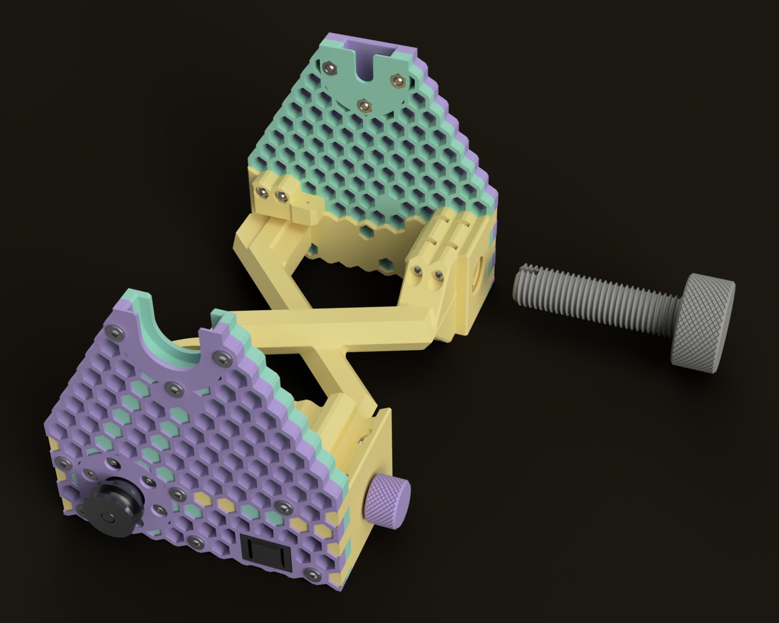
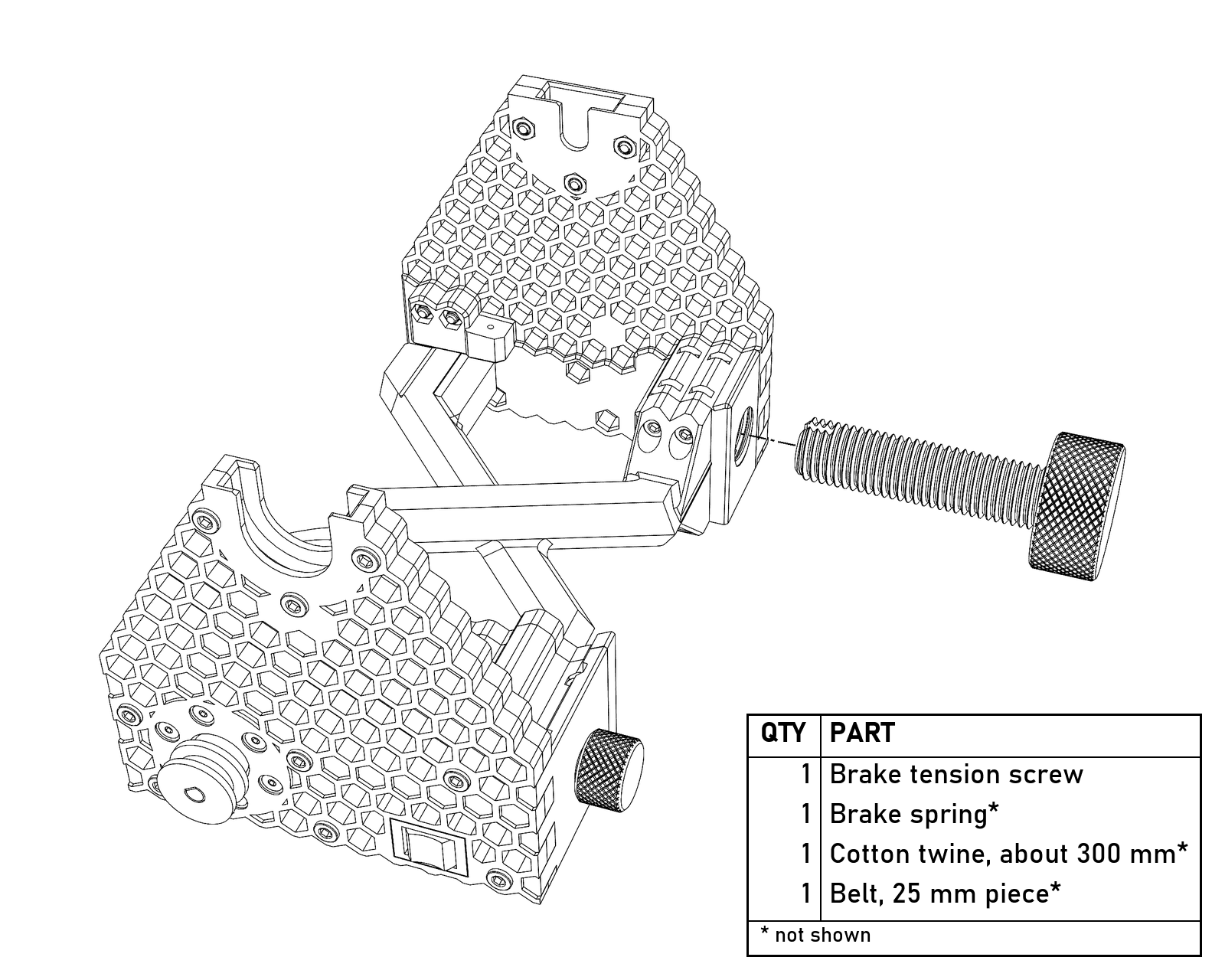
The brake tension screw threads into the brake screw retainer from the side. The spring, the twine and the piece of belt aren’t shown.
- Turn the brake tension screw until the slot in its end is about 25 mm (1″) out from the retainer, and tie about 300 mm (12″) of cotton twine (or your preferred brake material) to it by passing it through the slot and tying it around the threads.
- Tie the brake spring to the other end of the twine and hook it on the cup hook in the brake spring retainer.
- Screw in the brake tension screw to take up some of the slack, but leave enough to get the brake pulley on the bobbin under it.
- Slide the bobbin onto the flyer. If it doesn’t slide on smoothly, loosen the bobbin’s threaded joints, slide it all the way onto the rod to line up the bearings, and tighten them again.
- Slide a 608 over the end of the rod and set the flyer and bobbin in the base, with the brake line over the brake pulley on the back of the bobbin.
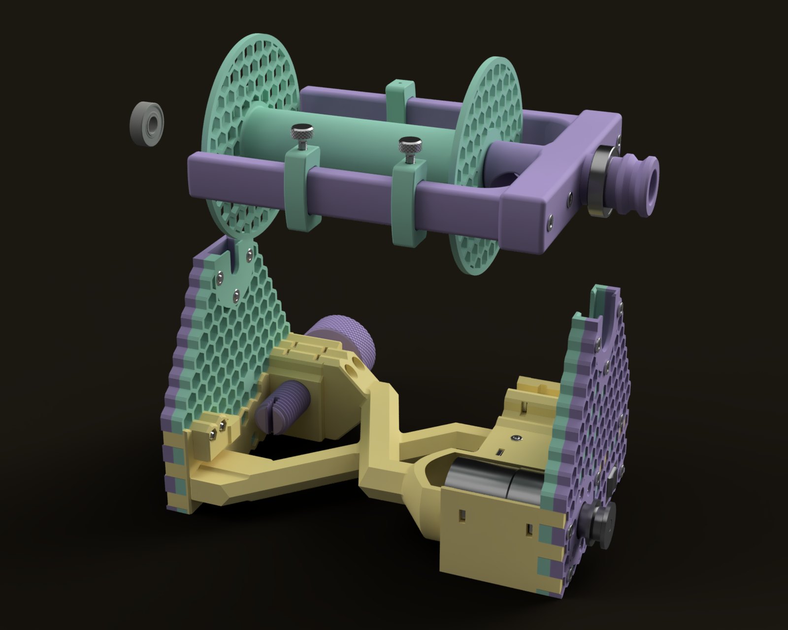
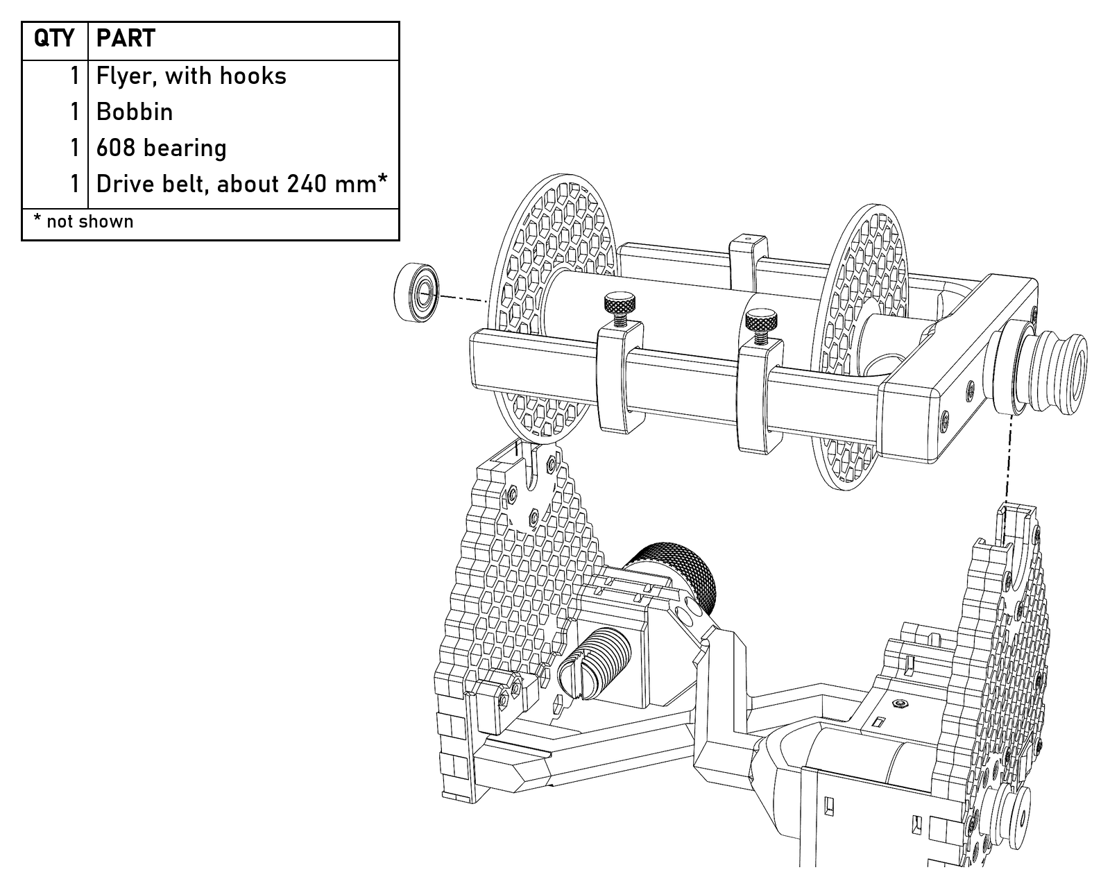
The flyer and bobbin drop straight down into the saddles, with a 608 on the end of the rod. The belt isn’t shown.
- Tighten the brake tension screw to take up the rest of the slack.
- Cut about 240 mm of belt and join the ends with your preferred method. I use a heat gun and a small jig, which is included in the print files.
- Put the belt on and do the final test.
- Spin stuff!
Changing bobbins
Take the belt off and lift the whole flyer straight up out of the base. Slide the rear bearing off the end of the rod, then slide the bobbin off. Putting it back is the reverse.
Files
The STEP model and printable assemblies are on Printables. Everything is CC BY-SA, so remix away, and tell me what you build, break, or improve.
Get the files on Printables →